Detailed description of the trailer model development can be found in Phase B report and Phase C report.
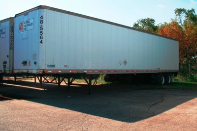
In order to obtain the most accurate geometric and structural properties of the trailers components for FE model development, a 14.6-m (48-foot), dual-tire, tandem axle 1990 Stoughton box trailer was purchased for purposes of disassembling, sectioning, and measuring key trailer model components. The result of this effort was a more comprehensive and accurate FE model of the semitrailer leading to better overall fidelity of the tractor-semitrailer FE model, as compared to full-scale crash test results.
The new trailer model was developed based primarily on the geometry of a 53-ft Stoughton trailer. The CAD geometry was obtained through a collaborative effort between research team and Digimation. Research team staff visited a local Freightliner dealer and surveyed the trailers on their lot. Photographs and measurements were taken and provided to Digimation for use in developing the CAD geometry. This geometry was then used by the research team to develop the FE mesh of the semi-trailer.
While the external appearance of the trailer model developed by the team appeared suitable, it was necessary to make multiple assumptions about the structure and geometry of key components that affect the structural behavior of the trailer. The research team purchased a used box trailer during Phase B and proceeded to disassemble, section, and measure key trailer model components to provide an accurate representation of the trailer.
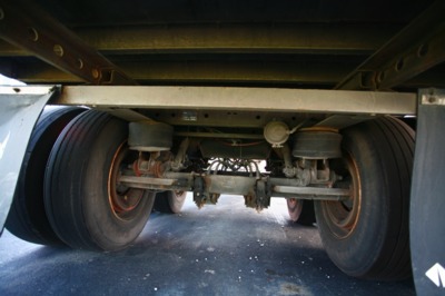
The original semi-trailer that was used to obtain detailed physical measurements for the initial FE model developed in Phase A of this project was a 16.2-m (53-foot), dual-tire, tandem axle 2004 Stoughton box trailer located on a Columbus, Ohio Freightliner dealer's lot. It was a 14.6-(48-foot), dual-tire, tandem axle 1990 Stoughton box trailer obtained from National Semi-Trailer Corp. in Columbus, Ohio, and was very similar structurally to the original semi-trailer. Both trailers were equipped with Airide suspension systems.
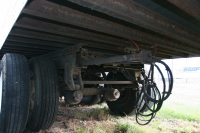
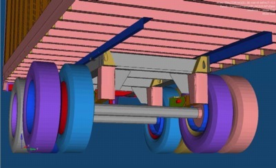
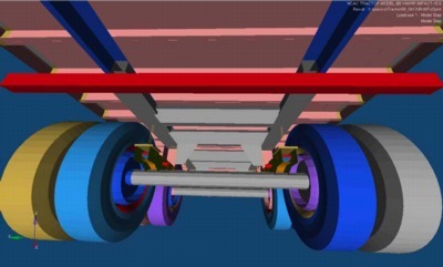
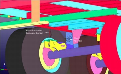
The trailers that the FE model was based on had airbag "Airide" rear suspension systems with a moveable wheelset (bogey) with fore-aft position adjustment. This wheelset consists of a longitudinal steel frame with four main crossmembers (called the slider subframe). It has two main axles with four (dual) wheels/tires on each axle and suspension pivot arms to accommodate movement of the airbag "springs" and shock absorbers.
The wheelset is attached to the cargo box via a sliding connection to allow for positioning of the trailer's wheels fore-aft for various loading conditions. This sliding connection is the (nested) interface of the wheelset's subframe (Z-channel) members with the cargo box main longitudinal frame (Z-channel) members. The wheelset is locked into position via two (fore and aft) 25.4mm (1-inch) diameter round lateral bars on the wheelset subframe that engage indexing holes in the cargo box main longitudinal frame Z-channel members.
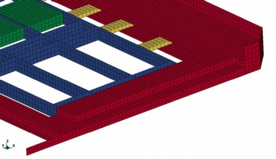
The floor of the cargo box is made up of longitudinally oriented oak wood planks bolted to, and supported on, laterally oriented steel I-beams. The main longitudinal cargo box frame that interfaces with the wheelset is welded to the laterally oriented steel I-beams.
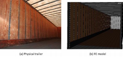
The side walls of the cargo box are assemblies of a riveted aluminum (or steel) outer skin, reinforced with galvanized steel vertical "hat-section" beams regularly spaced with 2-foot wide Ľ-inch plywood panels between them on the interior of the cargo area.
The front wall is similar in construction to the side walls; a riveted aluminum (or steel) outer skin, reinforced with regularly spaced galvanized steel vertical "hat-section" beams. The vertical beams support one large plywood panel on the interior of the cargo area.
The roof of the cargo box is thin sheet metal skin - typically aluminum, supported on laterally oriented "roof bows" - which are formed, galvanized steel (beam) sections. The roof bows are riveted to the upper side rails, and connected to the roof sheet metal with a flexible adhesive.
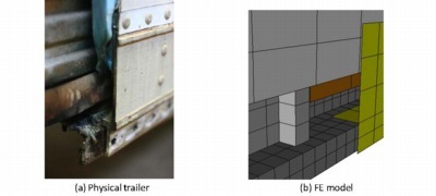
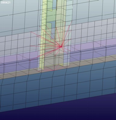
The Kingpin box is the heavily reinforced steel weldment at the front of the trailer that provides the structural support and strength for the Kingpin which is the main attachment point for connecting the tractor to the trailer. Since it is half the interface between the tractor and the trailer, the Kingpin box structural characteristics and stiffness will greatly affect the overall response of the tractor-trailer vehicle. Consequently, this component had to be represented correctly in the FE model.
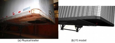
The overall dimensions and plate thicknesses of the Kingpin Box weldment were measured directly. Sketches were made and photographs were taken. The FE model was created directly from this information using HyperMesh.
LS-Dyna Type 16 fully-integrated thin-shell elements were used throughout this component. The element size was nominally 24 mm (1-inch) for all elements in the Kingpin Box Assembly. This size was chosen because it was reasonable for the geometry definition, it would not adversely affect (decrease) the current typical time step size, and it would provide appropriate mesh refinement for contact with the Tractor's fifth wheel.
The connectivity between all individual plates in the assembly was done using common-node connections. Individual plates in the weldment assembly were assigned unique *Part numbers to account for the various thicknesses and/or positions. The shell elements were assigned *Hourglass control type 8. The Kingpin Box material was characterized as AISI 8630 Steel using *Mat_Piecewise_Linear_Plasticity material model in LS-Dyna with a yield strength of 1,241 MPa. The Kingpin was specified as rigid material.
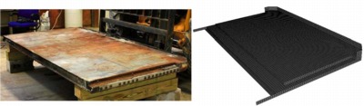
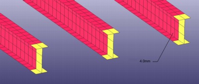
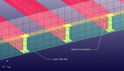
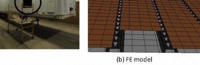
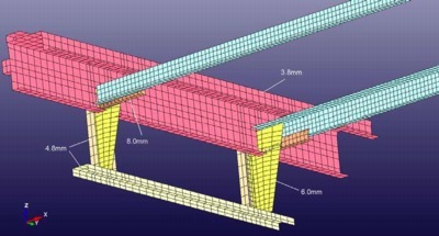
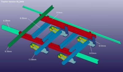
The main lateral cross beams are 100 mm (4-inch) tall steel I-beams (standard structural shapes) that run width-wise on a 300 mm (12-inch) spacing nearly the entire length of the trailer and support the wooden floor. These lateral cross beams were readily accessible for measurement and did not require dissection to obtain thickness and geometry.
This particular type of "hourglass control" used in conjunction with this fully integrated element type is actually a method to invoke the element's "full projection warping stiffness" to effect a true shell element formulation.
The overall dimensions and plate thicknesses of the Lateral Cross-Beams were measured directly. Sketches were made and photographs were taken. The FE model was created directly from this information using HyperMesh. LS-Dyna Type 16 fully-integrated thin-shell elements were used for the Lateral Cross-Beams. The element size was nominally 25 mm (1-inch) for the flange elements and ~30 mm (1.25-inch) for the web elements. This size was chosen because it was the minimum reasonable size to represent the geometry and it would not adversely affect (decrease) the current typical time step size.
The Lateral Cross Beams shell elements were assigned *Hourglass control type 8. The material specified for the Lateral Cross Beams was ASTM A653 Grade 80 with a yield strength of 550 MPa using the *Mat_Piecewise_Linear_Plasticity material model in LS-Dyna with no failure. The connectivity between the web and the flange was done with common-node connections.
The Lateral Cross Beams are connected to the Lower Side Rails using a tied shell edge contact.
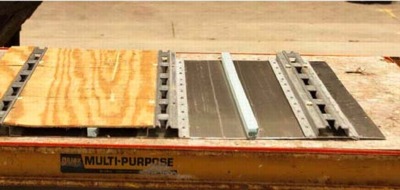
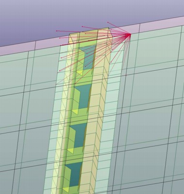
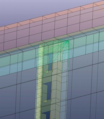
The side-wall structure is comprised of an outer aluminum "skin", vertically oriented steel formed "hat" beam sections, and multiple vertical plywood panels. The skin, vertical beams, and plywood panels are riveted together.
A representative 2-foot by 4-foot section was saw-cut from the side wall. The overall dimensions and plate thicknesses of the side-wall assembly were measured directly. Sketches were made and photographs were taken. The FE model was created directly from this information using HyperMesh. LS-Dyna Type 16 fully-integrated thin-shell elements were used throughout this component. Individual plates in the assembly were assigned unique part numbers to account for the various thicknesses and/or positions. The shell elements were assigned *Hourglass control type 8.
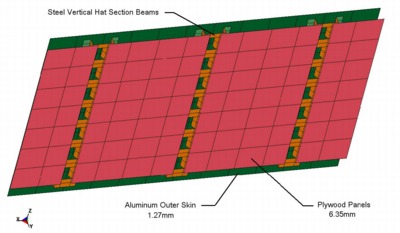
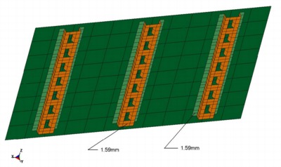
The element size was nominally 100 mm (4-inches) for the elements of the Outer Aluminum skin and the Plywood Panels. The element size was nominally 20 to 40 mm (0.75 to 1.5-inches) for the steel vertical hat-section beams. This element size was chosen because it was reasonable for the geometry definition and it would not adversely affect (decrease) the current typical time step size. These vertical beams were connected to the Outer skin and the Aluminum Panels via "solid weld-elements" using *Mat_Spotweld in Ls-Dyna.
The Aluminum skin was specified as 6061-T6 using the *Mat_Simplified_Johnson_Cook (strain-rate dependent) material model in LS-Dyna with no failure. The plywood panels were modeled using the *Mat_Elastic material model in LS-Dyna with a density of 681 Kg/M^3 (measured) and a Young's Modulus of 12,400 MPa (typical value for wood). The vertical hat-sections were specified as CS1040 steel and were characterized using the *Mat_Piecewise_Linear_Plasticity material model in LS-Dyna with a yield strength of 368 MPa and no failure.
The Side-wall's vertical steel hat-sections are connected to the Upper Side Rails and to the Aluminum outer skin via *Constrained_Nodal_Rigid_Body's (CNRB's).
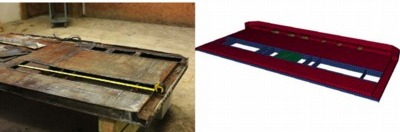
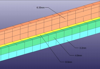
The upper and lower side rails are aluminum extrusions that provide the upper and lower longitudinal legs of the cargo box frame for the trailer. They are riveted to the inner and outer skins at the top and bottom of the cargo box. These rails were section-cut to provide access for measuring the details of the geometry of their cross sections so this structural detail could be accurately implemented in the FE model.
The overall dimensions and plate thicknesses of the upper and lower side rails were measured directly. Sketches were made and photographs were taken. The FE model was created directly from this information using HyperMesh.
The LS-Dyna material model used for the upper and lower side rails was *Mat_Piecewise_Linear_Plasticity. 6061-T6 Aluminum was specified with a yield strength of 276 MPa, and no failure.
LS-Dyna Type 16 fully-integrated thin-shell elements were used to model these components. The element size for the upper side rails was nominally 20 mm to 50 mm (0.75 to 2.0-inch) and 25 mm to 50 mm for elements in the lower side rail. These sizes were chosen because they were the minimum reasonable sizes for geometry definition and they would not adversely affect (decrease) the current typical time step size of the overall FE model.
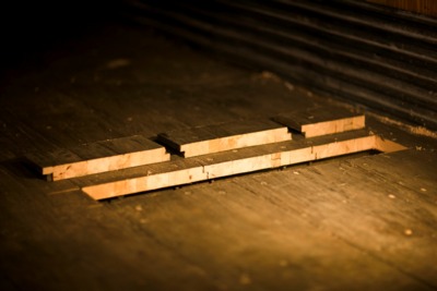
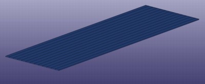
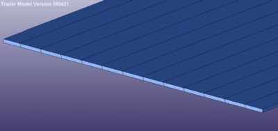
The wooden floor of the cargo box is comprised of 10-inch wide, 1.25-inch thick laminated oak planks oriented longitudinally across the full width of the trailer. The individual planks are butted together with step-joints and are bolted to the main lateral cross beams. A section was cut out of the floor to reveal these details.
The FE model's individual, longitudinally-oriented oak planks were modeled as separate pieces in contact with each other with one element through the thickness. The step-joint was simulated with a single slanted interface between the planks.
The oak floor was modeled using the *Mat_Elastic material model in LS-Dyna with a density of 736 kg/m^3 (measured) and a Young's Modulus of 12,400 MPa (typical value for wood).
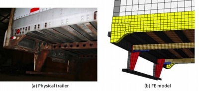
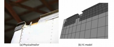
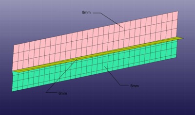
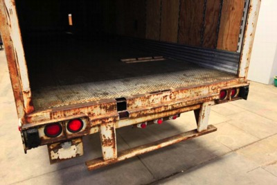
The rear bumper (and step) provides significant strength and rigidity to the rear of the trailer. This large weldment assembly was sectioned to obtain detailed geometry information and thickness.
The overall dimensions and plate thicknesses of the upper and lower side rails were measured directly. Sketches were made and photographs were taken. The FE model was created directly from this information using HyperMesh.
The material for the rear bumper was specified as SAE980X Grade 80 HSLA steel. The LS-Dyna material model *Mat_Piecewise_Linear_Plasticity was used to characterize the material using a yield strength of 557 MPa and no failure. LS-Dyna Type 16 fully-integrated thin-shell elements were used for all the components in the rear bumper except the weld elements. The element size for the rear bumper parts was nominally 25 mm to 50 mm (1.0 to 2.0-inch). These sizes were chosen because they were the minimum reasonable sizes for geometry definition and they would not adversely affect (decrease) the current typical time step size of the overall FE model.
The rear bumper parts with the trailer frame included to show the connection. Each part of the assembly is shown as a different color. The different parts were separate thicknesses.
The rear bumper components were connected to each other using common-nodes and LS-Dyna weld elements. LS-Dyna weld elements are implemented using solid elements with element connectivity specified to define the normal orientation of the welded connection. The *Mat_Spotweld material model is used to define weld-joint failure mode - if desired. The *Contact_Tied_Surface_to_Surface option is used to define the actual connection of the welded parts.

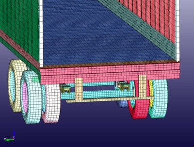
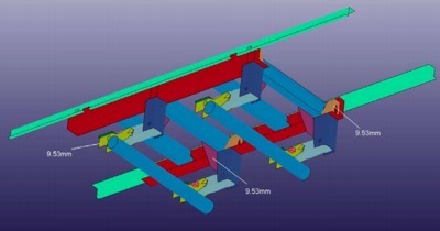
The rear frame is comprised of fixed longitudinal members that are welded to the lateral side beams. The bogie is comprised of the wheels, frame, tires and axles, and the suspension system of the trailer. The bogie is longitudinally adjustable by the driver/operator to accommodate various loading situations. The rear frame and bogie were accessible for measurement and did not require dissection to obtain component thickness and geometry - with the exception of the rear axles. A hole was drilled in one of the axles to obtain the axle tube's thickness.
The trailer suspension's spring and shock-absorber elements were implemented using LS-Dyna discrete elements (springs and dampers) - the Airide suspension system's air bag's properties and shock-absorber properties were copied from the tractor's suspension system which were obtained by physical testing described in the Phase A final report.
The overall dimensions and plate thicknesses of the rear frame and the bogie components were measured directly. Sketches were made and photographs were taken. The FE model was created directly from this information using HyperMesh.
LS-Dyna Type 16 fully-integrated thin-shell elements were used for most of the rear frame and the bogie components. Type 1 under-integrated and Type 2 fully-integrated solid elements were used for solid-like parts. The element size was nominally 25 mm (1-inch) for the frame elements, about 38 mm (1.5-inch) for the axle-tube and pivot-arm elements, and 50 mm (2-inches) for the wheel and tire elements. These sizes were chosen because it was the minimum reasonable size in each case to represent the geometry and it would not adversely affect (decrease) the current overall model time step size.
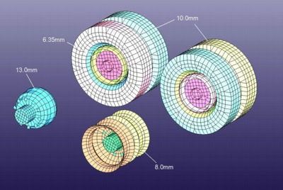
The shell elements were assigned *Hourglass control type 8 and the solid elements were assigned *Hourglass control type 1. The material specified for the frame components was SAE 950X HSLA Grade 50 with a yield strength of 340 MPa using the *Mat_Piecewise_Linear_Plasticity material model in LS-Dyna with no failure. The material specified for the axles was A500 Grade B structural steel tubing with a yield strength of 317 MPa using the *Mat_Piecewise_Linear_Plasticity material model with no failure. The material specified for the pivot arms was SAE 1095 steel with a yield strength of 776 MPa using the *Mat_Piecewise_Linear_Plasticity material model with no failure. The material specified for the wheel rims was mild steel with a yield strength of 270 MPa using the *Mat_Piecewise_Linear_Plasticity material model with no failure. The brake drums and the axle-ends / backing plates were specified as rigid materials with steel density. The material specified for the Tires was *Mat_Elastic with an elastic modulus of 2461 MPa. A thickness of 10 mm and a density of 3100 Kg/M^3 were specified to obtain a weight of 53.5 Kg (118 lbs) per tire.
The air pressure in the tires was specified as 0.69 MPa (100 psi). The air pressure in the tires was simulated using the *Airbag_Simple_Pressure_Volume option. Initially, the tire pressure was simulated using the *Airbag_Simple_Airbag_Model option, but was changed to the *Airbag_Simple_Pressure_Volume option for simplicity and better reliability because with the *Airbag_Simple_Pressure_Volume option, the tire pressure can be input directly rather than as a calculated result of multiple parameters. With the *Airbag_Simple_Airbag_Model, the tire pressure is calculated by LS-Dyna based on: mass flow in, air density, constant volume heat capacity, constant pressure heat capacity, temperature, ambient pressure, and the calculated internal energy. When the original *Airbag_Simple_Airbag_Model option was used with the existing parameters, the air pressure in the Tractor and Trailer tires calculated by LS-Dyna was 0.38 MPa (56 psi). The recommended tire pressure specified by the manufacturer is 0.38 MPa (100 psi).
In general, the connectivity within the rear frame, the wheels, and axles was done with common-node connections. The connection of the fixed-to-movable frames was sliding contact, with spotweld elements at four points fixed to the (moveable) bogie longitudinal frame rails, and in tied contact with the (fixed) trailer longitudinal frame rails. This will allow the user to move the bogie fore/aft without having to re-specify or reconnect CNRBs. The wheels were connected to the axles via spherical joints enabling them to rotate. The pivot arms are connected to the frame components via spherical joints enabling them to rotate.
The material assignment for the heavy truck trailer model consisted of three steps. The first was to determine the list of structural parts in the trailer and their organization as functional groups. The next was to determine the types of materials and their designation for each of the parts. As different manufacturers have different trailer designs and employ different materials, the first two steps resulted in several part and material assignment schemes. Trailer manufacturers generally do not reveal the specific material grades used for specific parts, so the search had to include original and aftermarket parts suppliers. The third step was to determine elastic and elasto-plastic mechanical properties for each material. The properties were then formatted in the input form for constitutive material models that can be used in LS-DYNA.
As it was not initially specified what type of trailer was going to be used in the simulations, two separate material assignments were developed for Aluminum and for steel trailer bodies. After a steel body trailer was purchased for the model development, the steel assignment was used in the final model.
From a structural perspective, designs of dry freight trailers are relatively similar across manufacturers. The top and bottom longitudinal rails at edges of the van are the primary structural components. The rails are connected into a space-frame by the rear frame, the (front) kingpin box, and the corner posts. The side posts, floor cross members, roof beams, and the trailer skin panels complete the box of the trailer and all participate in structural response. To accommodate higher load capacities, manufacturers commonly increase the size of the side rails. Some designs also employ extruded trailer sides with higher rigidity and structural participation.
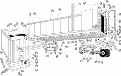
During the course of the project, a used trailer was purchased to provide more information for the model sub-assemblies. The purchased trailer was a steel dry freight trailer by Stoughton Trailers company. Their web site has an exploded parts diagram that was used for structural part classification and parts nomenclature in the FE model. Other parts suppliers also have vehicle diagrams and material assignments for different trailer configurations, which were used for the Aluminum-model version of the trailer.
Several web sites have downloadable parts catalogs with parts dimensions and limited material information . We also obtained a printed parts catalog from a trailer OEM supplier that specified grades of steel and Aluminum for the main structural parts. Great Dane Trailer's web site has product line catalogs that list the suppliers for trailer parts and substructures. Web sites of parts suppliers were searched for material assignments to the parts. As an example, various trailer door configurations can be found , such as laminated structures with wood or thermoplastic cores, skins made of galvanized steel, Aluminum alloys such as 3003-H14, 3105-H14, 5052-H34, or stainless steel such as 304-2B. Galvanized steel materials were typically of a product of US Steel, which is specified in their product line as ASTM A653 grade 80 structural steel, with minimum yield strength of 80 ksi and minimum tensile strength of 82 ksi.
Trailer rail, posts, corners, roof, and side panel material assignments were determined from reference . In Aluminum trailers, the extrusions (roof bows, side post, corner post, top and bottom rails, rub rails, J-moulding, cross members, front top radius, scuff, flooring) are made of Aluminum alloy 6061-T6. In steel trailers, channel forms are made of HSLA 80 ASTM A656 steel. The Bumper tube and the kingpin box is made of high strength steel with 80 ksi yield stress, HSLA 80 ASTM A656. Aluminum alloys 3105-H14, 3004-H291, 3004, 5052 are used for trailer side sheets. Roof sheets are made of Aluminum alloys 3003-H16, 3103B-H26, and 5052-H33. The Aluminum panels are joined using Aluminum buck rivets made from alloys 2117, 2117-T4, 6053, and 1100 head styles, or solid rivets of type 302HQ (ASTM A 493) for stainless steel panels. The floor panels [17, 19, 25] are usually made of laminated oak or treaded sheet of Aluminum alloys 3003-H22, 3003-H25, and 5086-H32. The kingpin material was listed in on-line brochures of the kingpin and suspension manufacturer as AISI 8630H steel hardened to Brinell Hardness 302-363 BHN.
The suspension of the modeled trailer consists of slider sub frame, different brackets, springs, axles, and wheels. The material for the slider sub frame of the wheelset assembly was listed in manufacturer's brochure as high strength steel with 80 ksi yield, which is most probably HSLA 80 ASTM A656 as this steel is used for frame materials due to the combination of its strength and formability. The standard materials for tractor and trailer leaf springs are heat treated SAE 5160, 1085, and 9260 steels . Leaf spring hangers are made of either formed high strength steel or cast steel . A reference found for trailer axles specifies trailer axle material as ASTM A 500 steel .
Several general reference books can be consulted for tractor and trailer parts . These were used to confirm the above assignments and to determine material assignments to parts that were not available from the OEM literature. This particularly pertains to smaller parts of the trailer such as suspension castings, spring hangers, axle suspension brackets, etc. The most comprehensive assignment information can be found in references. Steel fasteners were listed mostly as SAE Grade 5 and Grade 8.
The main objective of the trailer FE model is in large scale structural crash simulations, so the constitutive material models have to strike a reasonable balance between available information, model accuracy, model characteristics (e.g., element formulations, discretization), and computational cost.
Material properties required for the FE model are density, modulus of elasticity, Poisson's ratio, and non-linear elastic-plastic properties (yield stress, strain hardening).
The most commonly-used constitutive model in structural crashworthiness of metallic structures (using crash simulation code LS-DYNA ) is the piecewise linear elastic-plastic material model. In this material model, the plastic hardening curve is implemented as a monotonically increasing, piecewise linear curve relating effective plastic strain and effective plastic stress . One of the principal advantages of this model is that data from uniaxial tension or compression experiments can be directly used in the model after being converted to true stress - true strain form. This type of data is easily found in open literature. The data has to be processed to limit the number of linear segments for the desired accuracy and to eliminate spurious regions of strain softening. This material model formulation was used for metallic materials in the trailer FE model.
The material strength properties for the metallic materials used in the trailer FE model were primarily obtained from compilation of stress-strain data . The data for cast iron and steels was retrieved from standards , online databases , and reference books . The data for Aluminum alloys were taken from references . The data curves were scanned from the references and digitized. The digitized curves were converted into piecewise linear form by using an optimization algorithm that ensures that the resulting form will be within the prescribed error tolerance.
The trailer materials were implemented as a separate file to be included into the overall model. This simplifies material management and provides for reformulation of material properties in the model.