Correlation of Mechanical and
Optical Measurements of High Strain Rate Properties of Advanced High Strength
Steels
Srdjan Simunovic,
Donald Erdman and J. Michael Starbuck
Oak Ridge National
Laboratory
ORNL Testing Proposal
to Auto/Steel Partnership
Strain Rate
Characterization Project
April 5, 2007
1. Purpose and Background
In support of the Auto/Steel Partnership (A/S-P), Strain
Rate Characterization Project, ORNL will conduct a high rate experimental tests
and analysis of base material specimens in tension configuration. The objective of the test program is to
provide the necessary experimental data in support of the A/S-P efforts to
determine high-strain-rate mechanical properties of Advanced High Strength
Steels (AHSS). The experiments and data will also enable better predictive
modeling of base materials for finite element crash modeling. The test program will consist of
testing tensile specimens under strain rates of quasi-static, 0.1/s 1/s 10/s
100/s and maximum strain rates achievable in full open loop configuration and
the gage length. The tests will be conducted on the new hydraulic test
equipment at the Oak Ridge National Laboratory. All the tests will be conducted
using the same apparatus. The machine allows for testing at speeds from quasi-static
to 700 in/sec (18.5 m/s) over a range of 4 inches (100 mm) at maximum loads of
9000 lbf (40 KN). If an effective gage length for the chosen specimen is known
equipment can run non-linear velocities in the drive file to achieve global
strain control (engineering or true strain rate as desired).
The dynamic testing procedures from recent studies sponsored
by International Iron and Steel Institute [1,2] and published literature [3,4]
will be followed. High-speed video recording will be used for will provide
detailed record of the test and will be used for strain measurement correlation
to mechanical displacement data.
2. Scope of Work
2.1 Specimen Design
The dog bone-shape tensile specimen configuration will be
used. Configuration variation of laboratories labeled B and C from Reference 2
will be used. Specimens will be made by the ORNL. Specimen configuration must
accommodate for strain gage attachment in the load measurement section. Figure
1 shows schematics from Reference 3.
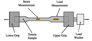
Figure 1. Tensile specimen
configuration
The necessity of installing backing plates will be
determined by the ORNL by conducting preliminary tests of specimens with and
without backing plates and evaluating the results. The preliminary results will
be evaluated jointly by A/SP and ORNL to determine specimen modifications. If
it is determined that the addition of backing plates is necessary, the plates
will be added by the ORNL.
2.2 Test Speeds
We propose to conduct test under 5 speeds in order to
achieve rates of : quasi-static, 0.1/s 1/s 10/s 100/s and maximum strain rates
of the order of 500+/s. Specimen gage lengths may need to be modified to
provide sufficient time for specimen equilibration under higher loading speeds
[1,2].
2.3 Test Instrumentation
Measurement of forces, displacements, stresses and strains
will be based on the instrumentation listed below. Tests at rates higher than
1/s will be recorded by a high-speed camera. Several lower rate tests will be
recorded during the test development to make sure that the measurement method
is consistent across different speeds.
Forces will be measured by:
- Equipment
load cell
- Equipment
load washer
- Calibrated
strain gage on the specimen tab [2, 3].
Strains will be measured by:
- Actuator
displacement,
- Optical
measurements from high-speed movies
- Strain
gage in the test gage region [2, 3].
The multiple measurement methods of both forces and
displacements will allow for correlation of the results and verification of the
method. All the measurements will be synchronized using the central trigger.
2.4 Test Materials
We propose to test seven different materials per A/SP
request. Materials are:
- DP980T/550Y
- DP980T/650Y
- DP780T/420Y
- DP780T/550Y
- DP590T/340Y
- DP500T/300Y
- 590R
Material thickness is to be defined by the A/SP. Thicknesses
up to 2 mm are possible. Thickness between 1.0 mm and 1.6 mm is preferred.
Tests will be conducted with 3 replicates for each rate and each material.
3. Deliverables
Deliverables will be text files, high-speed movies, analyzed
data and web-based presentation of the results similar to the current ORNL A/SP
project web site for tube crush and material data. See:
http://thyme.ornl.gov/ASP_Main/crashtests/crashtests.cgi
We will also provide a written Final Report documenting the
experimental procedure and test results.
The raw data from each test will be provided in an ASCII file format.
4. Schedule
The tests will be completed by September 30, 2007 provided
that the funds and materials are available during May 2007. The high-speed testing is not standard, and the
proposed project involves significant research component in instrumentation,
test configuration and test interpretation.
5. References
- Recommendations
for Dynamic Tensile Testing of Sheet Steels, International Iron and Steel
Institute, 2005. http://www.worldautosteel.org/pdf_hsrt/DynTestingRecomPract.pdf
- C.
Wong, IISI-AutoCo Round-Robin Dynamic Tensile Testing Project,
International Iron and Steel Institute, 2005. http://www.worldautosteel.org/pdf_hsrt/RptRndRobResults.pdf
- D.
Matlock, J. Speer, Constitutive Behavior of High Strength Multiphase Sheet
Steels Under High Strain Rate Deformation, AISI/DOE Technology Roadmap
Program, Report TRP 9904, 2005.
- D.M.
Bruce, Dynamic Tensile Testing of Sheet Steels and Influence of Strain
Rate on Strengthening Mechanisms in Sheet Steels, Ph. D. Thesis #
MT-SRC-003- 018, Colorado School of Mines, 2003.