Functionally and Geometrically Ordered Ti Armor
Computational Models for Ti Composite Armors
1: One-Dimensional Models for Armor
Standard layered and graded armor configurations have continuous translational symmetry in the plane of the armor. Their response during the early stages of projectile impact can be approximated by the one-dimensional shock and stress wave propagation models. The one-dimensional model assumes planar interfaces between the layers and uses method of characteristics for solving the shock equations and wave interactions. The computer program solves one-dimensional strain rate independent shock propagation equations and accounts for material non-linearity, interaction of elastic and plastic shock fronts, spalling, interface strengths, and many other impact-related phenomena.
The 1-D program is used for quick scoping of different armor configurations and investigating the effects of layer arrangements and gradations. Typical results are illustrated below for the simulation of impact of 5mm long steel projectile at 50 m/s into 10 mm thick barrier made from alternating layers of Al2O3 and Ti-6Al-4V.
- (Al2O3 + Ti-6Al-4V) x 1 Characteristics Diagram [image], Animation [mp4] [avi] [webm]
- (Al2O3 + Ti-6Al-4V) x 2 Characteristics Diagram [image], Animation [mp4] [avi] [webm]
- (Al2O3 + Ti-6Al-4V) x 4 Characteristics Diagram [image], Animation [mp4] [avi] [webm]
- (Al2O3 + Ti-6Al-4V) x 8 Characteristics Diagram [image], Animation [mp4] [avi] [webm]
2: Three-Dimensional FEM Model for Ballistic Impact Simulations
The three-dimensional ballistic impact simulations were conducted using the FEM code EPIC (Elastic-Plastic Impact Computations). The code functionality and algorithms are specialized for the analysis of high-velocity impact and has been extensively used in the military-related problems, with projectiles ranging from small-caliber bullets to large-caliber tank ammunition, and targets from body armor for soldiers to heavy armor for large tanks. An overview of the code capabilities can be found here.
The objective of our computational simulations are to investigate and evaluate new armor configurations that can be achieved using advanced manufacturing techniques, such as additive manufacturing. These new manufacturing methods may offer new impact defeating mechanisms that are not possible by the conventional manufacturing methods. In the direct manufacturing methods, the number of possibilities and the design space is enormous, so that it is more efficient for the armor designer to evaluate different concepts and materials using computational simulations, rather than using prototypes and tests. We are using the FEM models and simulations for explore new armor geometries and their variations.
2.1: Generation of Three-Dimensional FEM Models
The FEM models simulation of ballistic impact problems, must incorporate geometrical, material, loading, and deformation aspects of the problem. The deterioration, fragmentation and erosion of the target and the projectile introduce unique requirements on the modeling approaches and mathematical formulations. The FEM meshes for the ballistic impact simulations must consist of the 3-D brick elements or tetrahedral elements that are arranged in particular forms in order to avoid artificial stiffening (locking) of the models. For the modeling of fragmentation and erosion during impact, the 3-D brick elements need to be further partitioned into the symmetric arrangement of 24 tetrahedral elements that does not exhibit locking, and that can be eventually converted into fragments and particles.
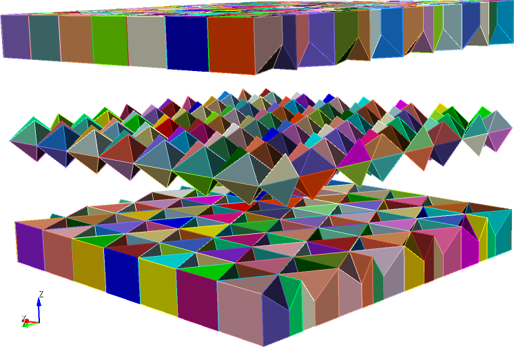
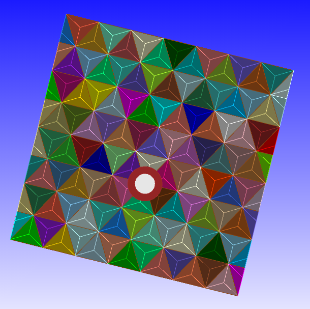
In the case of the FEM models of standard layered composites, the 3-D brick meshes naturally map onto the armor configurations. However, in the case of geometrically ordered composite armors, this mapping is not always straightforward and presents a major step in the model development. The 3-D brick mesh topology must conform to the complex geometrical patterns that does not always consist of cubic entities. An example of such geometrically ordered composite is shown below.
|
|
The composite armor is composed of two outer plates of Ti-6Al-4V with tetrahedral pyramidal indentations that act as the molds for the region of hard material within the pyramidal space.
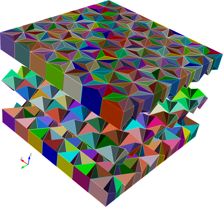
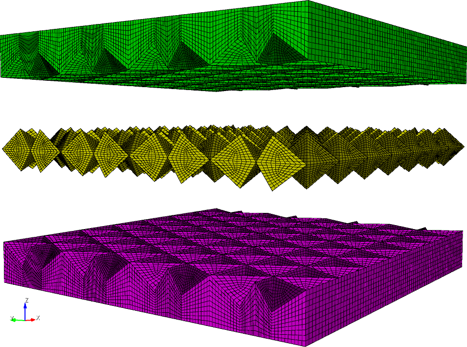
Building of an FEM model starts with generation of solid objects using geometrical relations in the composite. The solid objects are arranged so as to impose an overall mapping scheme that ensures all 3-D brick finite element mesh. The solid model objects are then discretized into the FEM mesh using the mapping rules that generate 3-D brick elements within each of the objects and merge them with the adjacent solid objects.
|
|
The bricks are converted to the tetrahedral elements in symmetric brick arrangement (24 tetrahedral within a brick, 4 elements per brick face, connecting into centroid location). The tetrahedral elements are required for modeling of fragmentation and material erosion.

|
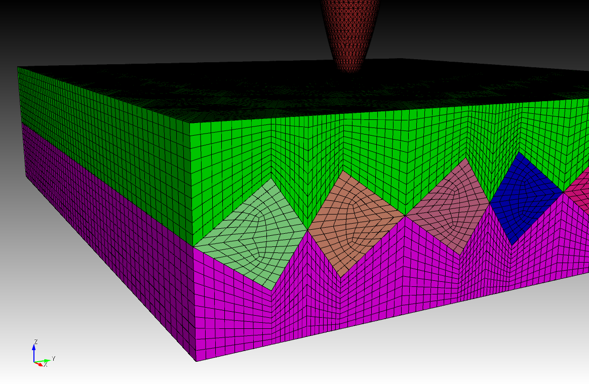
The projectile is the 0.30-Cal armor-piercing APM2 round . Material properties for the projectile and the target are derived from the literature and experiments.
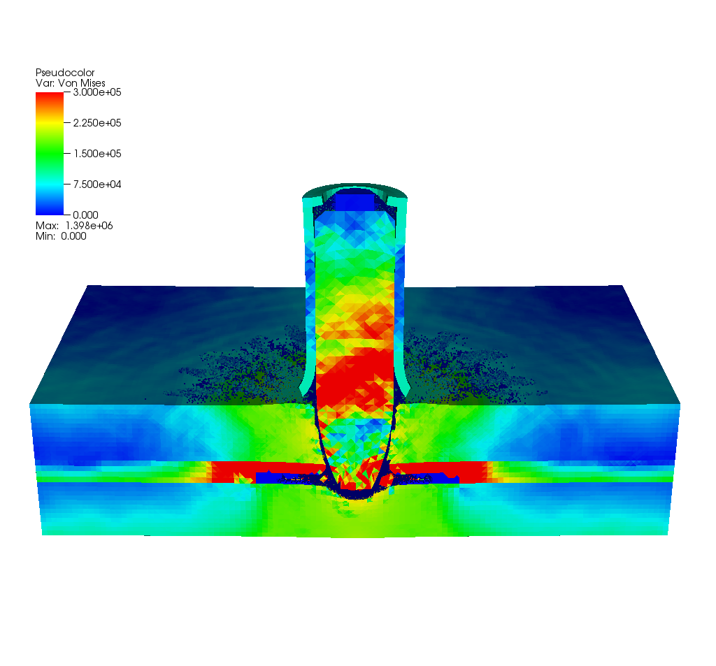
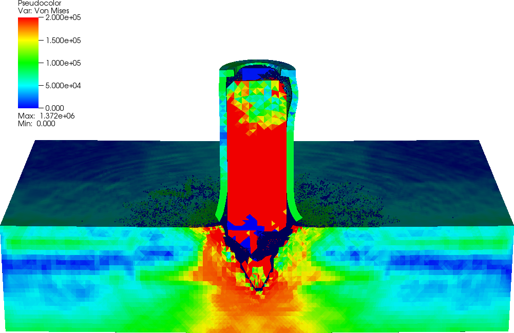
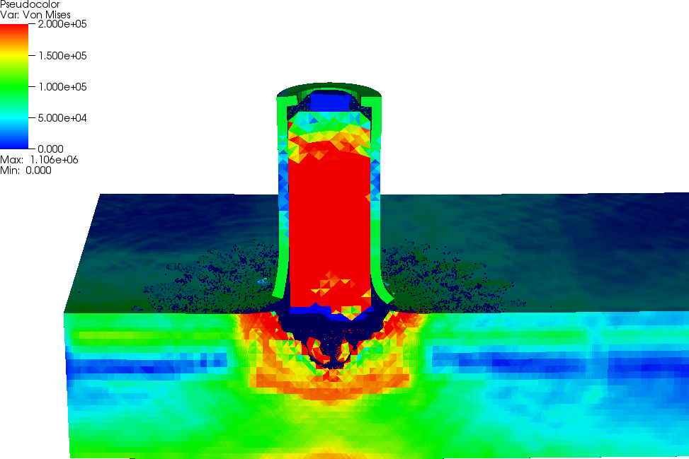
2.1: Projectile Impact into Homogeneous Ti-6Al-4V Plate
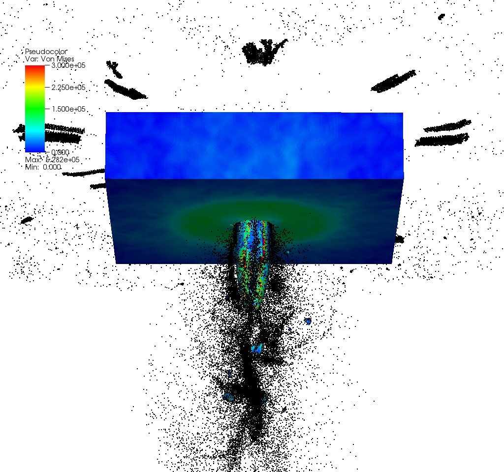
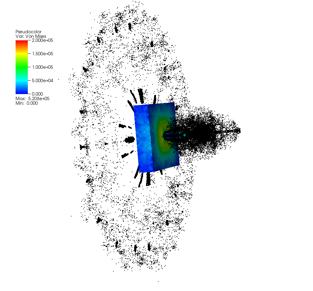
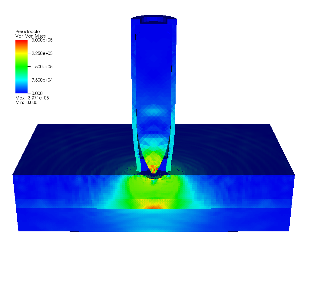
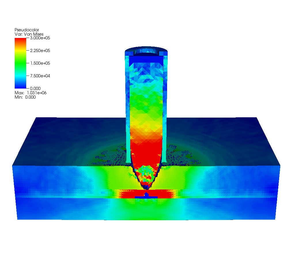
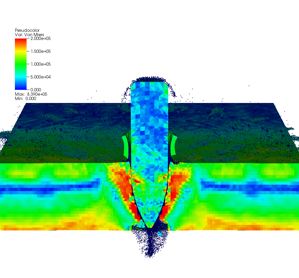
The following images show the simulation of the penetration of the homogeneous Ti-6Al-4V plate with the projectile impacting the plate at 2074 ft/sec.
Animation, Global [QuickTime Hi-Res] [WEBM Lo-Res] [AVI Lo-Res] [MP4 Lo-Res]
Animation, Cross-Section [QuickTime Hi-Res] [WEBM Lo-Res] [AVI Lo-Res] [MP4 Lo-Res]

|
|
|
|
|
|
|
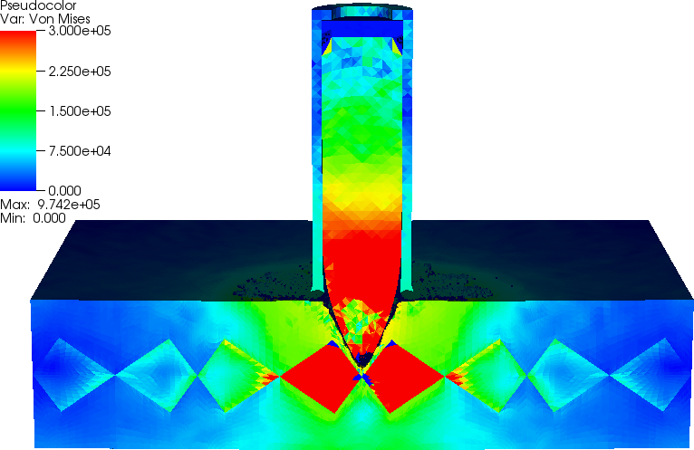
2.2: Projectile Impact into Layered Armor Plate
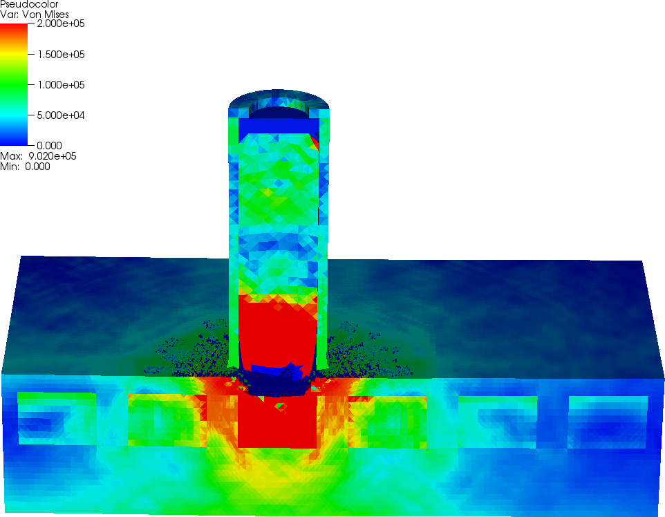
The following images show the simulation of the penetration of the layered armor plate with two layers of Ti-6Al-4V plate and a hard layer in the middle, with the projectile impacting the plate at 2074 ft/sec. The volume of the middle layer is equal to the volume of the material in the hard pyramids for the geometrically ordered armor composite with pyramidal inserts.
Layered Armor Plate
|
|
|

|

|
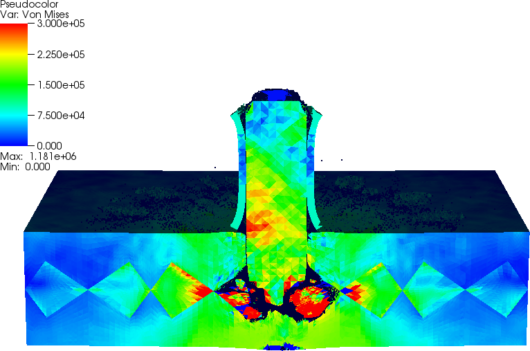
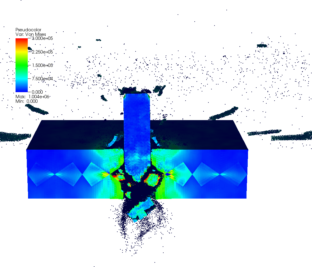
2.3: Projectile Impact into Geometrically Ordered Armor Composite, Pyramid Inserts
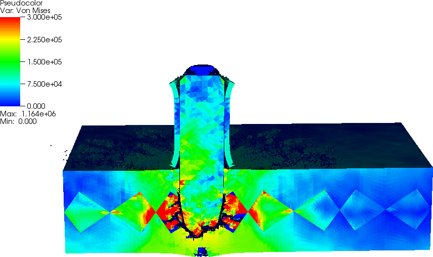
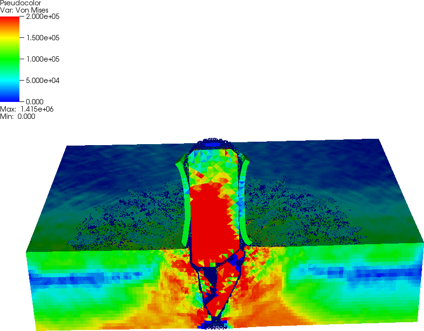
The following images show the simulation of the penetration of the geometrically ordered armor plate with two layers of Ti-6Al-4V plate and a hard layer in the middle, with the projectile impacting the plate at 2074 ft/sec.
Geometrically Ordered Armor Composite Plate, Pyramidal inserts
Animation, Global [QuickTime Hi-Res] [WEBM Lo-Res] [AVI Lo-Res] [MP4 Lo-Res]
Animation, Cross-Section [QuickTime Hi-Res] [WEBM Lo-Res] [AVI Lo-Res] [MP4 Lo-Res]

|

|
|

|
|
|
Because of the geometrical variations in armor configuration, various impact locations must be considered.

|
|
|
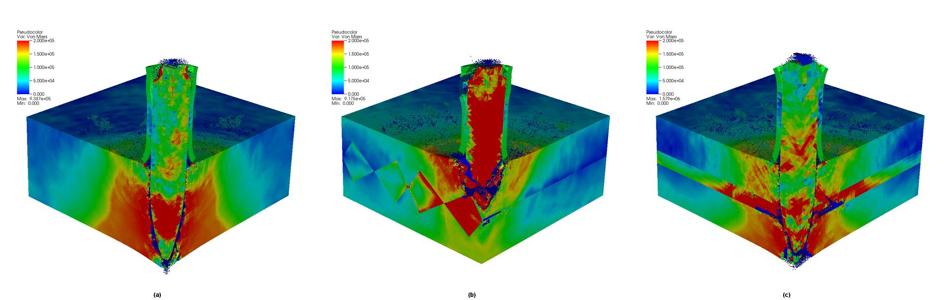
The simulations indicate that the geometrically ordered features can be used for improvement of the armor resistance to ballistic impact. The image below compares homogeneous Ti-6Al-4V (left), geometrically ordered composite with the hard insert (middle) and the layered configuration (right) having the equivalent volume of the hard material as the geometrically ordered composite.
|
2.4: Projectile Impact into Geometrically Ordered Armor Composite, Block Inserts
The following images show the simulation of the penetration of the geometrically ordered armor plate with Ti-6Al-4V material with hard block inserts in the middle, with the projectile impacting the plate at 2074 ft/sec.
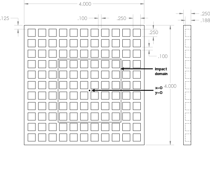
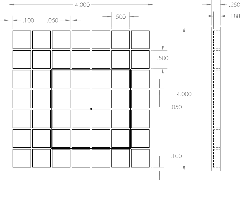
Geometrically Ordered Armor Composite Plate, Quarter Inch Size Hard Block inserts
|
The armor is constructed using one plate with geometry as shown in the image above, and another backing solid plate of the same thickness that is made of Ti-6Al-4V. The block regions in the first plate are filled with the harder material, capped with the second plate and consolidated into an integral armor plate.
|
|
|
Geometrically Ordered Armor Composite Plate, Half Inch Size Hard Block inserts
|
The armor is constructed using one plate with geometry as shown in the image above, and another backing solid plate of the same thickness that is made of Ti-6Al-4V. The block regions in the first plate are filled with the harder material, capped with the second plate and consolidated into an integral armor plate.
|
|