Simulation 2: Midwest Roadside Safety Facility Crash Test TL5CMB-2
The geometry of the tractor FE model was modified such that the wheelbase of the model was the same as the wheelbase of the test vehicle used in MwRSF Test No. TL5CMB-2. FE analysis was conducted simulating this test using the tractor-semitrailer FE model (model versions tractor_10-0520 and trailer_10-0521). The friction between the tractor and barrier was set to 0.2, and the friction between the tires and the barrier was set to 0.65. The dimensions of the barrier model were the same as those of the barrier in MwRSF Test No. TL5CMB-2 shown in Figure 1. Since there was negligible deflection of the barrier in the full-scale test, the barrier was modeled as a rigid material with rigid fixity to the ground. The impact conditions for the FE simulation were consistent with those reported in the full-scale crash test (i.e., 52.7 mph (84.9 km/hr) at an impact angle of 15.4 degrees).
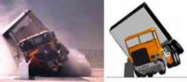
The ADAP program was used to aid in the modification of overall vehicle model size and shape parameters (e.g., wheelbase, trailer length). These scripts were designed to operate on the FE model input file directly and were used to modify the tractor model geometry. The ADAP scripts were used to: 1) make the sleeper-cab tractor a day-cab style tractor by removing the sleeper section of the cabin and 2) adjust the wheelbase length of the tractor by removing a section of the frame rails (along with other components in this section of the model).Visual comparison between the tractor FE model and the test tractor
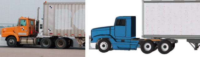
The most notable differences between the test vehicle and modified FE model are:
- Length dimensions – The length dimensions of the FE model were all within 2% of the test vehicle dimensions, except for the distance from the front bumper to the center of the front wheel (e.g., dimension “B” in Figure 5), which was 13.5% shorter in the FE model.
- Trailer box dimensions – The trailer floor in the FE model was 5.8 inches (148 mm) higher than the test vehicle (e.g., dimension “L” in Figure 5), and the top of the trailer in the FE model was 6.7 inches (169 mm) lower than the test vehicle (e.g., dimension “W” in Figure 5).
- Ballast center of gravity (c.g.) – The c.g. of the ballast in the FE model was located 23.6 inches (600 mm) rearward of and 4.6 inches (188 mm) higher than the c.g. location of the ballast in the test vehicle.
- Trailer suspension – The suspension system on the FE trailer model was the Airide™ design, and the suspension on the trailer test vehicle was a leaf-spring design.
Although the mass of the test tractor was not reported, it was estimated to be 15,526 lb (7,043 kg) by considering that the total gross static mass of the test vehicle was 28,819 lb (13,073 kg) and that the typical mass of a 48-ft (14.6-m) semitrailer is approximately 13,300 lb (6,030 kg). For comparison, the mass of the FE tractor model was 15,271 lb (6,927 kg). The axle loads of the FE model were within 10% of the axle loads measured on the test vehicle. The total mass of the FE tractor-semitrailer model was 79,807 lb (36,200 kg), which was 0.1% higher than the total mass of the test vehicle.
The analysis was conducted with a time-step of 1.20 microseconds for a time period of 3.0 seconds.
The suspension systems on the tractor and trailer models were initialized based on the weight of the model; however, the model was not at steady state at the beginning of the analysis. The tractor-semitrailer model was positioned at 15.4 ft (4.7 m) upstream of the impact point at the start of the analysis to allow 0.2 seconds for gravity to sufficiently load the suspension of the tractor and trailer prior to impact. The trailer’s response is somewhat affected by the additional vertical dynamics associated with the sudden ‘drop’ of the ballast under gravity.
Movies
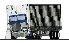 Front view (2.9MB) | 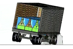 Rear view (2.9MB) |
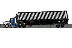 Side view (2.9MB) | 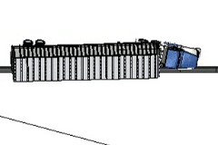 Top view (2.8MB) |
 Combined view front (0.3MB) | 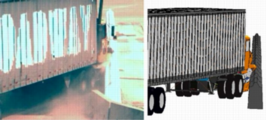 Combined view rear (0.2MB) |
